How USB cables work?
The working principle of a data cable may seem simple, but it involves intricate electrical engineering and communication principles. It primarily serves two main tasks: power transmission and data signal transmission.
It can be thought of as an efficient “dual-lane highway system for energy and information.”
1. Working Principle of Power Transmission (Charging)
This part is relatively straightforward, following basic physical laws such as Ohm’s Law.
Establishing a Voltage Difference: The power adapter (charger) converts mains electricity (220V AC) into the low-voltage direct current required by the device (e.g., 5V, 9V, 12V). This creates a voltage difference between the power source (charger) and the device (phone).
Forming a Closed Circuit: When the data cable is connected, it completes a closed circuit.
Current Path: Current flows from the positive terminal (VCC wire) of the charger → through the power wire core inside the data cable → into the device’s battery → then from the device’s ground terminal → through the ground wire (GND) inside the data cable → back to the negative terminal of the charger.
Regulation and Negotiation (Key to Smart Fast Charging): In modern fast-charging technologies, the process is not fixed:
The device (phone) and the charger communicate through the data wires (D+ and D-) in the data cable or a dedicated configuration channel (CC wire, unique to Type-C interfaces) using communication protocols such as PD or QC.
They negotiate the highest voltage and current combination supported by both parties (e.g., 9V/2A).
Only after successful negotiation does the charger output higher voltage, enabling fast charging.
An E-Marker chip is read during this stage to ensure the data cable itself can handle the high current and power after negotiation.
Simple Analogy: Power transmission is like using a water pipe to fill a pool. Voltage is like water pressure, current is like the flow rate of water, and the data cable is the pipe itself. The thicker and better the pipe (low-resistance oxygen-free copper), the lower the resistance, and the smoother the flow (current), resulting in faster filling (charging).
2. Working Principle of Data Signal Transmission
This part is the core of the technology, essentially involving digital communication.
Nature of Digital Signals: Devices like phones and computers process digital signals composed of “0s” and “1s.”
Voltage Level Representation: In the data cable, these “0s” and “1s” are represented by different voltage levels. For example, in USB 2.0:
0V ~ 0.3V may represent the digital “0”
2.8V ~ 3.6V may represent the digital “1”
Differential Signal Transmission (Key to Anti-Interference): This is the foundation of modern high-speed data transmission. For example, USB uses a pair of twisted wires (D+ and D-) to transmit data.
The sender transmits two signals that are opposite in phase but equal in amplitude.
The receiver detects the voltage difference between these two wires rather than their individual voltages relative to the ground.
Advantage: External electromagnetic interference (EMI) typically affects both closely spaced wires simultaneously and equally. When the receiver calculates the voltage difference, the interference signals cancel each other out, significantly improving anti-interference capability and signal integrity.
Protocol Control: Raw data cannot be sent haphazardly. Before transmission, data is packaged into data packets following specific communication protocols (e.g., USB protocol). These packets include information such as the target address, data content, and error-checking codes.
Reception and Decoding: The chip at the receiving end reads the voltage signals, converts them back into binary data of “0s” and “1s,” unpacks the data packets according to the protocol, checks for errors, and finally sends the valid data to the device’s processor.
Simple Analogy: Data transmission is like two people communicating with “flag signals” on a noisy battlefield (an environment full of electromagnetic interference). One person simultaneously raises both hands, moving the left and right hands in completely opposite motions (differential signals). The person far away focuses only on the difference between the motions of the two hands to interpret the information. Even if smoke and dust (interference) make both hands appear somewhat blurry, their relative difference remains clear and discernible.
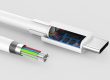
3. How Do the Components Work Together?
Combining its internal structure, the working principle is as follows:
Interface (Terminal): Acts as the “toll booth” and “entry ramp,” ensuring correct physical connection. The E-Marker chip within it provides the “pass” (cable capability information).
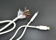
Copper Core Wires: Are the “highway” itself, responsible for carrying current and signal voltage.
Shielding Layer: Acts as the “soundproof walls and guardrails” along the highway, blocking external “noise” (electromagnetic interference) and preventing the cable’s own signals from interfering with other devices.
Insulation Layer: Serves as the “divider” between lanes, preventing “lane crossing” (short circuits or crosstalk) between the power, ground, and data wires.
Outer Sheath: Is the “roadbed and pavement” of the highway, protecting all internal structures from physical damage.
Summary
The working principle of a data cable is a sophisticated process that combines electrical engineering (providing energy) and digital communication (transmitting information).
Charging relies on voltage difference and a low-resistance circuit, with smart protocol negotiation enabling efficient fast charging.
Data transmission relies on voltage levels representing binary data and uses differential signal technology to resist interference, ensuring high-speed data flow is accurate and error-free.
A high-quality data cable provides an optimized channel for these two tasks through its physical structure (wire core material, shielding, insulation) and chip support (E-Marker). In contrast, poor-quality data cables can cause slow charging, data errors, and unstable connections due to high resistance, lack of shielding, and inferior chips.