The Composition and Structure of Data Cables
The structure of a data cable is far more complex than it appears. It is the product of precision engineering, and its design directly determines its performance (charging speed, data transfer speed) and durability.
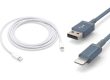
A high-quality data cable typically consists of three main parts: the connector (plug), the cable (wire), and the jacket (outer sleeve).
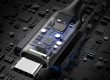
1. Connector (Plug)
This is the part that connects the data cable to the device and is the most precise component.
Shell (Housing)
-
Material: Usually plastic (ABS, PC) or metal (zinc alloy, stainless steel). Metal shells are sturdier and offer better heat dissipation, often used in high-end cables.
-
Function: Protects the internal terminals (PIN pins), provides structural strength during plugging and unplugging, and offers some shielding.
Terminals (Contacts / PIN Pins)
-
Material: Typically phosphor bronze or brass, plated with gold or nickel.
-
Function: These are the final contact points for current and data signal transmission. The plating prevents oxidation, ensuring stable contact and resistance. Gold is more oxidation-resistant and offers better conductivity than nickel.
-
Pin Definitions: Taking the common USB-A as an example, it usually has 4 pins:
-
VCC (+5V): Power positive
-
Data-: Data negative
-
Data+: Data positive
-
GND (Ground): Power ground
More advanced interfaces like Type-C have more pins to support reversible plugging, higher power, and faster speeds.
-
PCB (Printed Circuit Board)
-
Function: In complex connectors (e.g., Lightning, Type-C), the terminals are not directly connected to the wire cores but are first soldered to a miniature PCB, which then connects to the wire cores. This reinforces the structure and ensures electrical connectivity.
E-Marker Chip (Electronically Marked Cable)
-
Location: Hidden inside the head of Type-C and other connectors.
-
Function: This acts as an “ID card” for data cables supporting USB 3.1 Gen2 and above, USB4, or high-power fast charging (100W/5A and above). The chip stores the cable’s specifications, such as supported transmission protocols, maximum current, voltage, and data transfer rates. The device reads this chip to determine whether to enable high-speed or high-power charging modes. Cables without an E-Marker chip are typically limited to lower power and speeds.
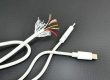
2. Cable (Wire) – The Most Complex Part
The internal structure of the cable is multi-layered, including from the inside out:
Conductors (Wire Cores)
-
Material: The core channels for current transmission, typically made of high-purity oxygen-free copper (OFC), which has low resistance and good conductivity. Low-quality cables use copper-clad aluminum (CCA) or impure copper, which have higher resistance, leading to slower charging and severe heat generation.
-
Structure: Usually composed of multiple finely stranded copper wires, making them more flexible and less prone to breakage.
Insulation Layer
-
Material: Each independent wire core is wrapped in a layer of polyethylene (PE) or polyvinyl chloride (PVC) insulation material.
-
Function: Prevents short circuits by ensuring the wire cores do not come into direct contact.
Shielding Layer
This is critical for ensuring data signal transmission quality, especially for high-speed data transfer. Typically, there are two layers:
-
Aluminum Foil Shielding: Wrapped around each group of wire cores (e.g., data wire groups), primarily defending against high-frequency interference.
-
Braided Shielding: A mesh layer made of tinned copper wires, wrapped around the outermost layer of all wire cores, mainly defending against low-frequency interference and providing physical protection.
-
Function: The shielding layer acts like a “Faraday cage,” effectively isolating external electromagnetic interference (EMI) and preventing internal signals from radiating out and interfering with other devices.
Drain Wire
A bare copper wire in contact with the shielding layer, used to guide interference signals collected by the shielding layer to the ground wire, thereby dissipating them.
Tensile Fiber (Strength Member)
-
Material: Usually a nylon thread or Kevlar fiber.
-
Function: Embedded in the cable core, it primarily bears pulling force, protecting the fragile copper wires from breaking and significantly enhancing the cable’s durability. This is a key indicator of a high-quality cable.
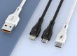
3. Jacket (Outer Sleeve)
Materials:
-
PVC (Polyvinyl Chloride): Low cost, relatively stiff, average feel, and not very bend-resistant.
-
TPE (Thermoplastic Elastomer): More environmentally friendly, softer, elastic, bend-resistant, and currently the mainstream material for mid-to-high-end cable jackets.
-
Braided Jacket: A layer of nylon, polyester, or other braided material wrapped over TPE or similar materials, significantly enhancing the cable’s wear resistance and tensile strength while improving its appearance and feel.
Summary: Structural Checklist of a High-Quality Data Cable
| Part | Component | Main Materials | Function |
|---|---|---|---|
| Connector | Shell | Plastic/Metal | Structural protection, shielding |
| Terminals (PIN Pins) | Gold/Nickel-plated Phosphor Bronze | Electrical connection | |
| E-Marker Chip | Silicon | Identifies cable capabilities (advanced features) | |
| Cable | Wire Cores | Oxygen-Free Copper | Transmits current and data signals (core function) |
| Insulation Layer | PE/PVC | Prevents short circuits | |
| Shielding Layer | Aluminum Foil + Braided Mesh | Resists electromagnetic interference (ensures signal quality) | |
| Tensile Fiber | Nylon/Kevlar | Enhances tensile strength, prevents breakage | |
| Jacket | Protective Layer | TPE/Braided Nylon | Insulation, protects internal structure, resists wear |
The next time you pick up a data cable, you will know that it is not just a simple “wire”, but a modern technological product composed of multiple materials and sophisticated structures, designed for efficient energy and information transmission.